FPDR valve
FEATURES
Available modifications for various purposes::
- normally open (fire-retarding) valve closes during a fire, blocking the spread of fire and combustion products through the ventilation ducts;
- normally closed (smoke) valve opens during a fire. It is used in supply and exhaust smoke ventilation systems.
General information
Available with a fire resistance limit of 120 minutes. The fire resistance limit of the FPD-120 valve:
• in normally open mode (fire-retarding) of valve - EI 120
• in normally closed mode (smoke) of valve - EI 120, E120
BASIC CONFIGURATION
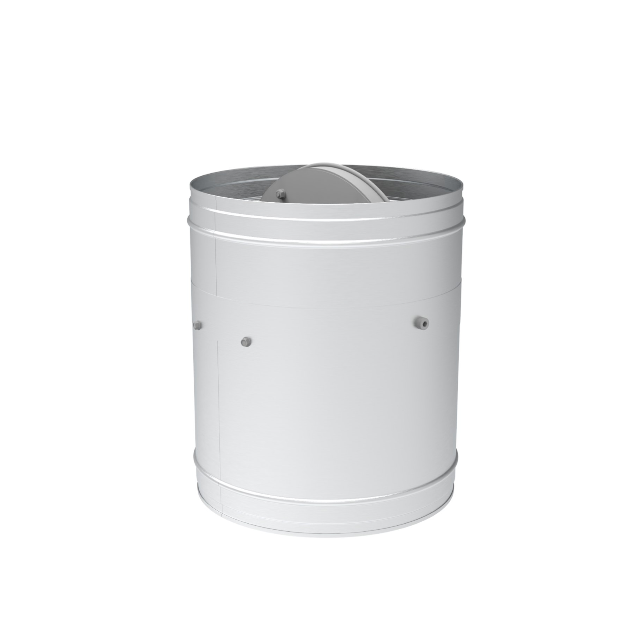
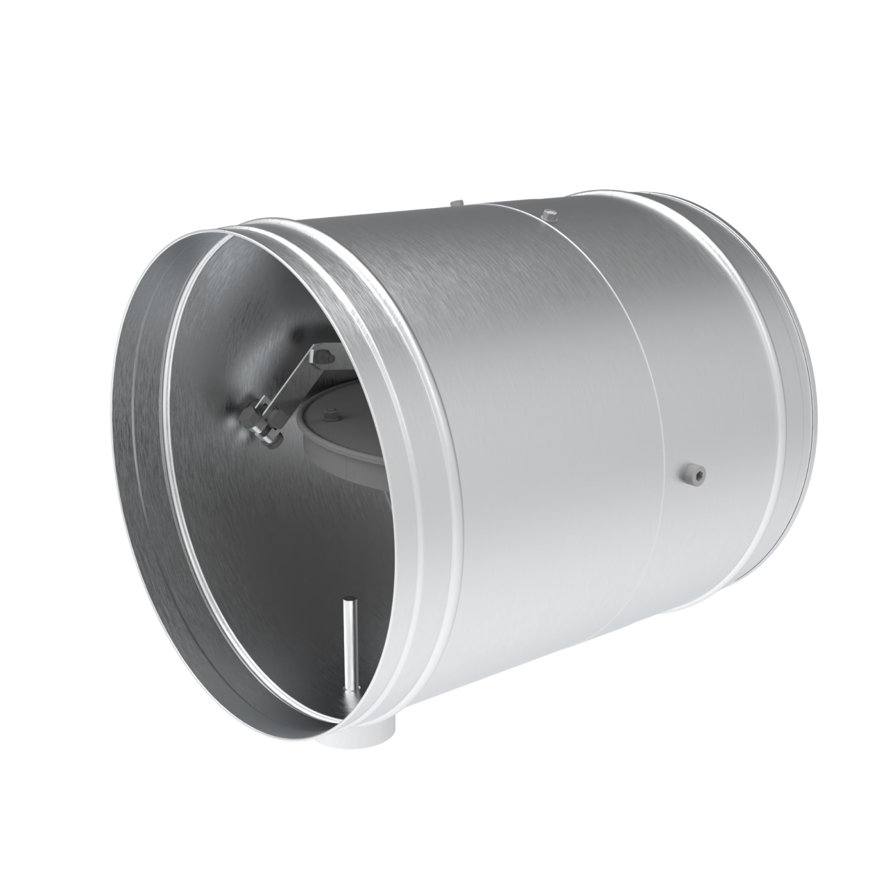
Design and materials
The valve case is made of galvanized steel from a European manufacturer. The rotary plates are covered with a fire-resistant material. Along the perimeter of the rotary blade is a thermosetting seal, which expands at high temperatures impact and thus provides a high tightness of the closed valve. Actuators of valves are installed outside the case. The damper of the valve automatically blocks the air flow with the rotational spring of actuator.
Application
Designed for installation in ventilation ducts, to prevent the spread of fire and combustion products from one room to another by blocking the ducts in accordance with relevant norms and standards.
For functional purposes are used in accordance with the requirements of Building norms and regulations 2.04.05, National construction regulations B.1.1-7 in heating, ventilation and air conditioning systems in civil and industrial buildings and structures, in emergency smoke ventilation systems, to remove smoke in case of fire to ensure evacuation of people from the premises or buildings at the initial stage of a fire that broke out in one of the premises.
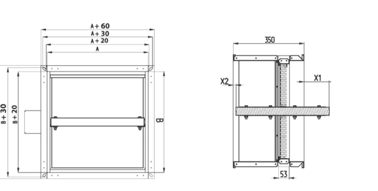
DESIGN SCHEME OF FPD RECTANGULAR VALVE
Valves are allowed for operation in a non-aggressive environment when the temperature exceeds + 35°C and relative humidity up to 80% in rooms with explosion-proof environment.
THE VALUE OF DAMPER OUTLET FROM THE CASE OF FIRE VALVE

X1 – damper outlet at the inlet to the valve, mm;
X2 - damper outlet at the outlet of the valve, mm. During designing of ventilation systems, it is necessary to take into account the outlet of the damper.
Before and after the valve it is necessary to design a straight section of the air duct with a cross section equal to the cross section of the valve, and a length equal to the outlet of the valve.
FPD valves, which do not have the value of the outlet of the blade X2 (up to B <500 m="" can="" be="" equipped="" with="" a="" protective="" net="" and="" can="" be="" used="" for="" shaft="" installation="" --500--="">
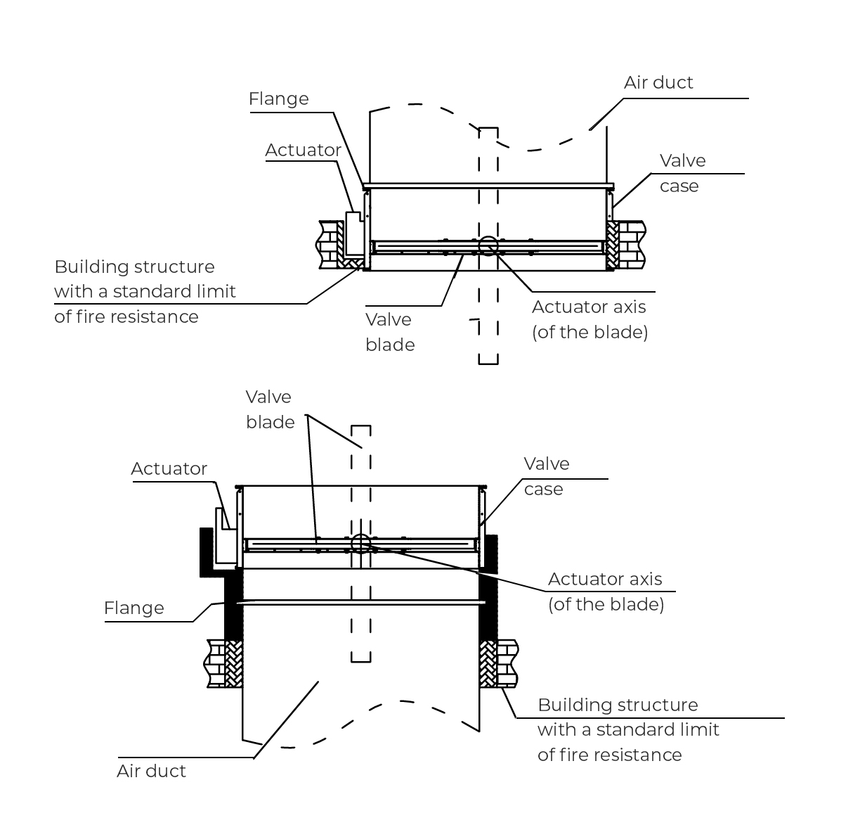
Installation.
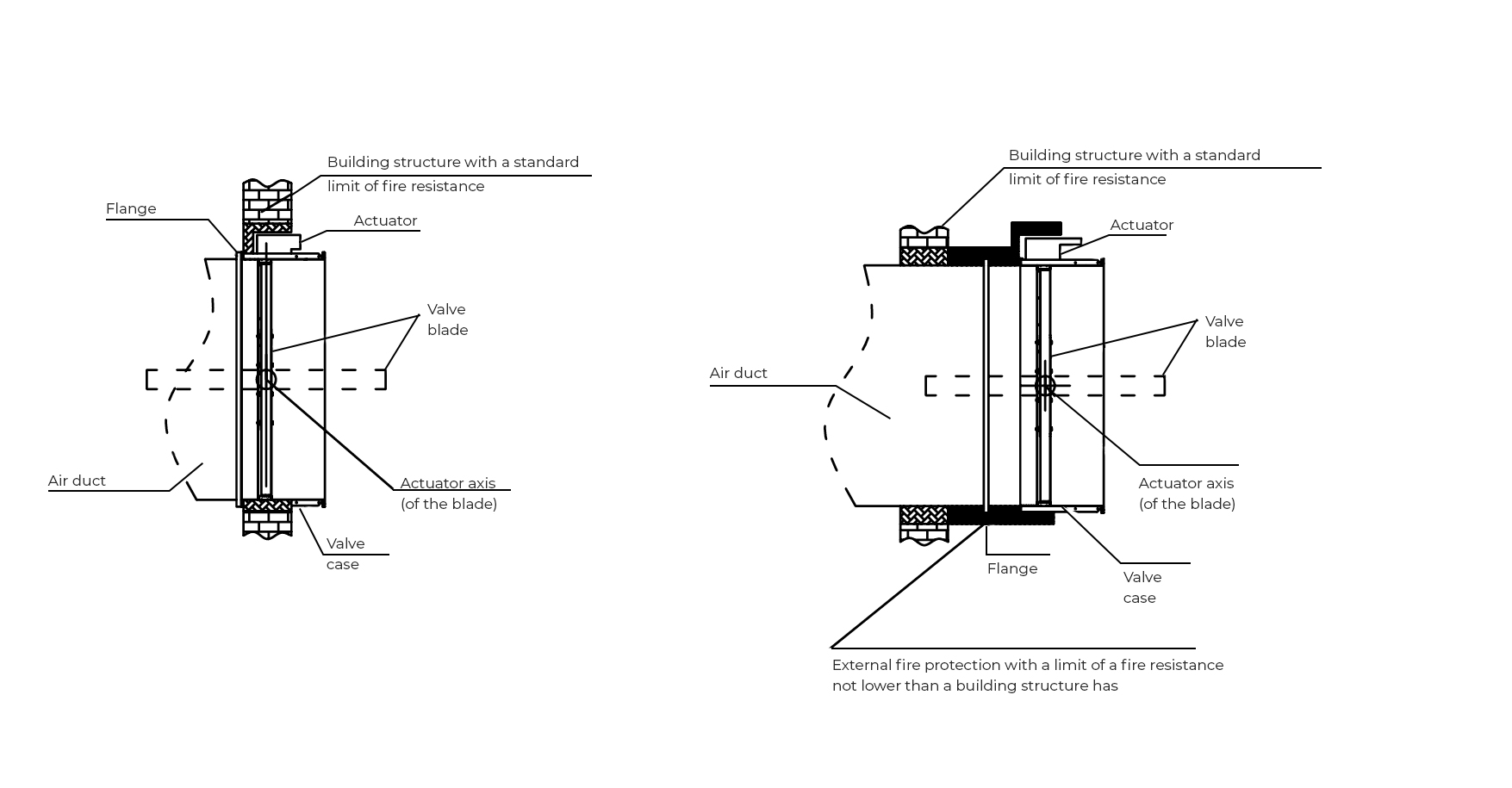
Valves can be installed in any position in vertical and horizontal passages of fire-preventing separating structure. The valve must be installed in such a way that the valve damper (in the closed position) is located in plane with the fire-preventing separating structure. If such installation is not possible, the valve case between the fire-preventing separating structure and the valve damper must be insulated with fire-fighting material in accordance with current standards.
INSTALLATION IN VERTICAL STRUCTURES
INSTALLATION IN FLOOR STRUCTURES